

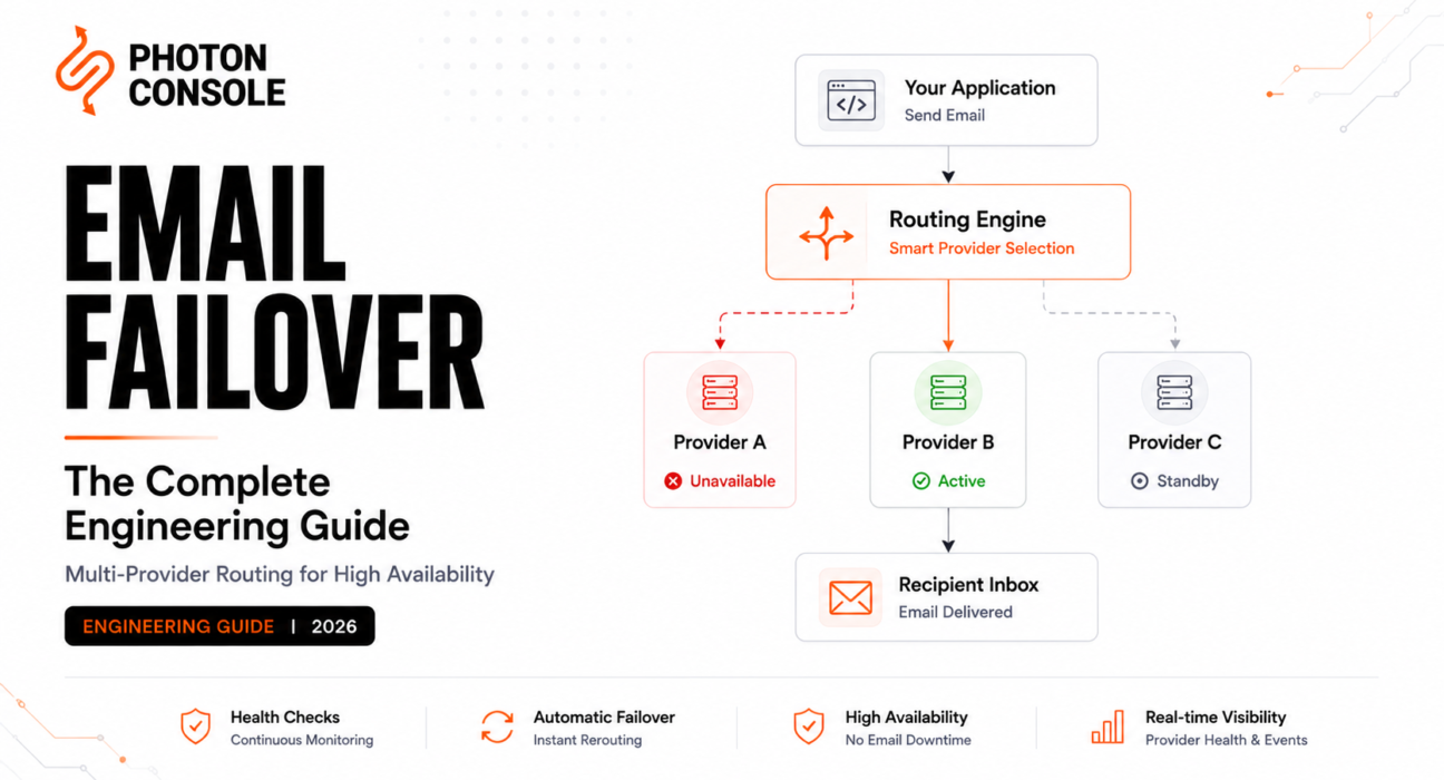
Every transactional email system has the same single point of failure, and most engineering teams don’t discover it until it breaks: the provider. Not the code, not the queue, not the DNS — the external service that actually delivers the message once your system hands it off.
Provider outages happen. Not often, but on a timeline measured in months rather than years, and usually at the worst possible moment — a peak traffic window, a product launch, a billing run — because those are the moments that stress every system in the chain simultaneously. A team that runs a single email provider with no failover path will, eventually, have a conversation with their CTO that begins with “how long were password resets down?”
Engineering Snapshot: During a major SMTP provider’s multi-hour partial outage in early 2025, teams with single-provider architectures experienced complete email delivery failure for the duration. Teams with multi-provider failover continued operating — some with no customer-visible impact at all — because their routing layer switched traffic automatically within seconds. The difference was not which provider they chose. It was whether they’d designed for the failure.
This guide covers how to design that infrastructure: multi-provider routing, automated failover, health checking, and the architectural patterns that turn a provider outage from a company-wide incident into a monitoring alert that resolves itself.
The core thesis throughout: reliable transactional email is not achieved by choosing the “best provider.” It is achieved by designing infrastructure that continues operating even when any individual provider experiences a partial or complete failure. We’ll call this the Infrastructure Survivability Framework — the idea that your email system’s availability target should be higher than any single provider’s SLA, which is only achievable if the system can survive the loss of any one component.

Why Email Downtime Happens
Email delivery failures are rarely total, which makes them harder to detect and harder to explain than a clean outage. The common failure modes:
- Provider-side API degradation — the API accepts requests but delivery is delayed or partially failing. Your monitoring sees 200 responses; recipients see nothing.
- Regional infrastructure failure — a specific datacenter or cloud region goes down, affecting delivery to recipients whose MX servers route through that region.
- Rate limiting under load — your provider’s rate limits cap delivery exactly when you need throughput most (a billing run, a security incident requiring password resets).
- Reputation-based delivery failures — a shared IP pool’s reputation degrades due to another sender’s behavior, and your mail starts landing in spam or being deferred by major mailbox providers. This is an IP strategy problem, but it manifests as a delivery failure.
- DNS propagation or resolution failure — your provider’s sending domain or MX lookup infrastructure has a DNS issue, and delivery attempts fail at the resolution step before SMTP even begins.
- Maintenance windows — planned or unplanned, sometimes coinciding with your own peak traffic.
None of these require your code to be wrong. None of them are in your control. All of them are in your architecture’s control, if the architecture was designed to handle them.
What Is Email Failover?
Email failover is an infrastructure pattern where a transactional email system automatically routes messages through an alternative provider when the primary provider is unavailable, degraded, or failing to meet delivery expectations. The system detects the failure (via health checks, error responses, or delivery metrics), reroutes traffic, and continues delivering messages with minimal or zero interruption to recipients.
This is the same high-availability pattern used throughout distributed systems engineering — database failover, CDN origin failover, DNS failover — applied specifically to the email delivery layer.
Why One Provider Is Never Enough
Table 1: Single Provider vs Multi-Provider Architecture
| Property | Single Provider | Multi-Provider with Failover |
|---|---|---|
| Availability ceiling | Limited by provider’s SLA (typically 99.9%) | Can exceed any individual provider’s SLA |
| Blast radius of provider outage | Total — all email delivery stops | Partial or zero — traffic reroutes |
| Rate-limit ceiling | Fixed to one provider’s limits | Aggregate of all providers’ limits |
| Recovery time | Dependent on provider’s incident resolution | Seconds to minutes (automated switching) |
| Architectural complexity | Low | Medium-High |
| Operational overhead | Low | Medium — multiple integrations, multiple monitoring targets |
A 99.9% SLA means roughly 8.7 hours of allowed downtime per year. For a password-reset system or an OTP delivery flow, 8.7 hours is not an acceptable annual budget — especially since those hours tend to cluster during incidents rather than distributing evenly. Two independent providers, each at 99.9%, give you a composite availability ceiling north of 99.99% if the failover itself is reliable, because the probability of both failing simultaneously drops by an order of magnitude.
Common Failure Scenarios
Table 2: Failure Types and Failover Response
| Failure Type | Symptom | Detection Method | Failover Action |
|---|---|---|---|
| Complete API outage | HTTP 5xx or connection refused | Health check; API error rate spike | Immediate route to secondary provider |
| Partial degradation | Elevated latency, intermittent errors | Latency threshold; error-rate threshold | Gradual traffic shift or circuit breaker trip |
| Rate limiting | HTTP 429 responses | Response code monitoring | Overflow to secondary; queue remainder |
| Deliverability degradation | Rising bounce/deferral rates from webhooks | Webhook event analysis | Shift traffic; investigate root cause |
| DNS resolution failure | Send attempts fail at resolution | DNS health checks | Route to provider with independent DNS |
| Regional outage | Failure scoped to specific datacenter/region | Geographic health checks | Route to provider in unaffected region |
Deliverability degradation is the most insidious failure on this list because it doesn’t produce error codes — the API accepts the message, the provider attempts delivery, and the message silently lands in spam or gets deferred. Catching it requires monitoring email observability signals from webhook events, not just HTTP response codes. This is also where SMTP monitoring tooling earns its operational value — the monitoring layer needs to see downstream delivery outcomes, not just upstream API health.
High Availability Principles
Before diving into specific routing patterns, the underlying principles that make email failover actually work:
- Provider independence — each provider must be independently reachable, with no shared dependency (shared DNS infrastructure, shared cloud region, shared authentication service) that could fail them simultaneously.
- Deterministic routing — the routing layer must decide which provider handles each message based on clear, observable signals, not on implicit assumptions about which provider is “primary.”
- Idempotent delivery — because failover can involve retrying a message against a different provider, the system must handle the possibility of duplicate delivery attempts gracefully (this intersects directly with SMTP retry logic design).
- Observable state — the routing layer’s decisions must be logged, metriced, and alertable, so the team knows when failover is happening, not just that it could happen.
Active-Passive Architecture
In an active-passive setup, all traffic flows through a single primary provider under normal conditions. A secondary provider is configured, authenticated, and ready but receives zero traffic until the primary fails. When failure is detected, the routing layer switches all traffic to the secondary.
Table 3: Active-Passive Trade-offs
| Advantage | Disadvantage |
|---|---|
| Simple to reason about — one active path at a time | Secondary provider is untested under real load until the moment you need it most |
| Lower cost — only one provider carries real traffic | Cold-start risk: secondary may have a cold IP or stale configuration |
| Easier monitoring — one active provider to watch | Switchover latency — detection + routing change takes time |
The critical risk with active-passive is the cold-secondary problem: if the secondary provider has a dedicated IP that hasn’t been warmed, or an SMTP configuration that hasn’t been validated recently, the failover itself can create a new failure — you escape one outage and land in a deliverability incident. Mitigating this requires sending a small trickle of real traffic through the secondary at all times, which blurs the line between active-passive and active-active.
Active-Active Architecture
In an active-active setup, traffic is distributed across multiple providers simultaneously under normal conditions. Each provider carries a fraction of production traffic (e.g., 70/30, 50/50, or weighted dynamically). When one provider degrades, its share redistributes to the others.
Table 4: Active-Active Trade-offs
| Advantage | Disadvantage |
|---|---|
| No cold-secondary risk — every provider carries real traffic | Higher integration and monitoring complexity |
| Failover is a weight adjustment, not a full switch | Higher base cost — multiple providers billing simultaneously |
| Natural load balancing across providers’ rate limits | Requires careful traffic segmentation to avoid reputation confusion |
| Continuous validation that both paths work | Webhook processing must handle events from multiple providers |
Active-active is the more resilient pattern, and the one most SRE-oriented teams converge on at scale. The complexity cost is real — you’re operating two (or more) provider integrations, two webhook processing pipelines, and a routing layer that needs to make per-message decisions — but it eliminates the class of failures where the secondary provider isn’t actually ready when you need it.
Priority Routing
Priority routing is a refinement of active-active where different traffic types are assigned different provider preferences. Password resets and OTPs route through the provider with the strongest deliverability track record for those use cases. Billing notifications route through the provider with the best cost profile. Marketing-adjacent lifecycle emails route through whichever provider handles that traffic type best, isolated from the transactional path.
This is the Routing Confidence Model: instead of treating all traffic identically, the routing layer expresses a per-traffic-type confidence score for each provider — based on recent delivery metrics, latency, error rates, and historical performance — and routes each message to the provider with the highest current confidence for that message type. When confidence in a provider drops (health check failure, rising error rate), its traffic shifts automatically.
Health Checks
Health checks are how the routing layer knows when to act. They should evaluate both the API layer and the delivery layer:
- API health — synthetic sends to the provider’s API at regular intervals, checking response time, status codes, and whether the request is actually accepted (not just acknowledged). This catches API outages and degradation.
- Delivery health — monitoring webhook event streams for delivery confirmation rates, deferral rates, and bounce rate trends. This catches the class of failures where the API is fine but delivery is failing downstream. Your observability layer feeds directly into this.
Table 5: Health Check Signals
| Signal | What It Detects | Action on Threshold Breach |
|---|---|---|
| API response latency > threshold | Provider degradation | Begin gradual traffic shift |
| API error rate > threshold | Provider outage or partial failure | Trip circuit breaker |
| Webhook delivery confirmation rate dropping | Downstream delivery failure | Investigate + shift if confirmed |
| Bounce rate spike (from webhooks) | IP/domain reputation issue or provider-side misconfiguration | Shift traffic; investigate root cause |
| Health-check synthetic send failed | Provider completely unreachable | Immediate failover |
Automatic Provider Switching
Detection without action is monitoring, not failover. The routing layer needs a mechanism to actually redirect traffic once a health check signals a problem. Two patterns:
- Configuration-driven switching — the routing layer reads provider weights or active/passive state from a configuration store (a feature flag service, a key-value store, or a config endpoint) that an operator or an automated system can update. Fast to implement; requires either a human or a separate automation system to make the decision.
- Self-healing switching — the routing layer itself evaluates health signals and adjusts weights automatically, without operator intervention. More complex to build, but recovers faster because there’s no human-in-the-loop delay. This is the pattern you want for failures that happen outside business hours.
Retry Logic
Failover retry logic operates at a different layer than SMTP-level retry logic. SMTP retries happen after the message reaches the provider — the provider handles deferred messages according to its own retry schedule. Failover retries happen before the message reaches a provider, or when the primary provider’s API rejects or times out the request.
Table 6: Retry Strategies for Failover
| Strategy | When to Use | Risk |
|---|---|---|
| Retry same provider with backoff | Transient errors (timeouts, 503s) | Delays delivery if the failure isn’t transient |
| Immediate failover to secondary | Definitive errors (connection refused, persistent 5xx) | May trigger failover on a transient blip |
| Retry same, then failover | Balanced approach (1–2 retries, then switch) | Slightly higher latency; usually the best default |
| Fan-out to multiple providers simultaneously | Ultra-critical messages (security alerts) | Duplicate delivery risk; requires dedup |
The “retry same, then failover” pattern is the practical default for most teams: one or two fast retries absorb transient blips without triggering a full provider switch, and a definitive failure after retries triggers the switch cleanly. Fan-out (submitting the same message to multiple providers simultaneously) is warranted for the very narrow set of messages — security-critical alerts, time-sensitive OTPs — where a duplicate delivery is less costly than any delivery delay.
Circuit Breakers
A circuit breaker prevents the routing layer from continuing to send traffic to a provider that’s consistently failing, avoiding the slow bleed of retries and timeouts against a dead endpoint. The pattern: after N consecutive failures or an error rate exceeding a threshold within a time window, the circuit “opens” and all traffic routes away from that provider. After a cooldown period, the circuit “half-opens” — a small number of probe requests are sent to check if the provider has recovered. If they succeed, the circuit closes and traffic resumes. If they fail, the circuit stays open.
This is standard distributed systems engineering (the pattern is well-documented in the resilience engineering literature), applied to the email routing layer specifically. The key tuning decision is how aggressive the trip threshold should be: too sensitive and you’ll failover on normal variance; too lenient and you’ll keep sending traffic to a failing provider for minutes before switching. The right threshold depends on your traffic volume and your tolerance for delayed messages during the detection window.
Observability
We call this layer the Email Availability Pyramid — the observability signals that, stacked together, give you a complete picture of whether your email infrastructure is actually available to end users:
- Base layer: API health — is each provider’s API accepting requests and responding within acceptable latency?
- Second layer: delivery confirmation — are webhook events confirming that accepted messages are actually being delivered to mailbox providers?
- Third layer: recipient experience — are messages reaching inboxes (not spam folders), and are they arriving within acceptable latency for the use case?
- Top layer: business-level delivery — are the specific message types that matter most (OTPs, password resets, billing) delivering at their required SLAs?
A system can be “up” at layer one while failing at layer three — the API is healthy, messages are being accepted, but they’re landing in spam because of a reputation issue on the sending IP. A failover system that only monitors layer one will miss this entirely. Full observability means monitoring all four layers, continuously, for each provider in the routing pool.
Monitoring Failover
The failover system itself needs monitoring — not just the providers it routes to. Key signals:
- Failover event count and frequency (is it triggering more often than expected?)
- Traffic distribution across providers (does it match the intended routing weights, or has a silent failover shifted everything to the secondary?)
- Circuit breaker state per provider (open, half-open, closed)
- End-to-end delivery latency per provider (is a provider technically “healthy” by API metrics but adding latency that degrades the user experience?)
A failover that triggers without anyone noticing is working correctly. A failover that triggered three days ago and nobody noticed is a monitoring gap — the system is running on its secondary path, and if the secondary fails too, there’s no fallback left.
Recovery Procedures
Failover is half the system. Failback — returning traffic to the primary provider after it recovers — is the other half, and it’s often handled with less rigor.
- Automated failback — the circuit breaker’s half-open state probes the recovered provider, and if probes succeed, traffic gradually returns. This is the cleanest pattern but requires confidence in the health-check’s ability to distinguish genuine recovery from a temporary improvement.
- Manual failback — an operator reviews the provider’s status, confirms recovery, and manually adjusts routing weights. Slower, but eliminates the risk of premature failback into a not-fully-recovered provider.
- Gradual failback — traffic returns to the recovered provider incrementally (10% → 30% → 50% → 100%) with monitoring at each stage. This is the production-grade pattern: it catches partial recovery without exposing the full traffic volume to a provider that might relapse.
Testing Failover
A failover path that hasn’t been tested under real conditions will fail the first time it’s needed in production — this is true of every HA system, and email is no exception. Testing approaches:
- Chaos engineering for email — deliberately blocking the primary provider’s API (via network policy, firewall rule, or configuration change) and confirming that the secondary provider picks up traffic within the expected timeframe. Run this in production, during low-traffic windows, with the team watching.
- Scheduled failover drills — periodically switching the primary and secondary (or adjusting active-active weights to simulate a provider loss) and verifying that delivery continues, monitoring alerts fire correctly, and recovery procedures work.
- Synthetic transaction monitoring — continuously sending test messages through each provider and verifying delivery, independently of production traffic. This catches configuration drift (an expired API key, a stale SMTP configuration) before it matters.
Production Architecture
Putting it all together, a production-grade multi-provider email system has these components:
- Application layer — your code submits a send request to an internal email service, not directly to a provider.
- Routing layer — receives the request, evaluates provider health, applies routing rules (traffic type, priority, weight), and selects a provider.
- Provider adapters — provider-specific integration code (API client, authentication, payload formatting) behind a common interface, so the routing layer doesn’t need to know which provider it’s talking to.
- Queue layer — durable queue (SQS, RabbitMQ, Kafka) between the routing layer and the provider adapters, so a provider failure doesn’t lose messages. This is the same durability principle described in our queue architecture guide.
- Webhook ingestion layer — receives delivery events from all providers, normalizes them into a common schema, and feeds them into monitoring, alerting, and the health-check system.
- Health check and circuit breaker layer — continuously evaluates each provider’s health and adjusts the routing layer’s decisions.
The internal email service abstraction (component 1) is the most important architectural decision: it decouples your application code from any specific provider, which is what makes failover, migration, and multi-provider routing possible without application-level changes. Teams that call a provider’s SDK directly from application code can’t add failover without touching every call site.
Table 7: Architecture Component Responsibilities
| Component | Responsibility | Failure Behavior |
|---|---|---|
| Internal email service | Accept send requests from application code | Queue locally if routing layer is unavailable |
| Routing layer | Select provider based on health, weights, traffic type | Fall back to default provider if health data unavailable |
| Provider adapters | Translate common interface to provider-specific API | Return structured error to routing layer |
| Queue | Durable message storage between routing and delivery | Messages persist; retried after recovery |
| Webhook ingestion | Normalize and process events from all providers | Queue events; process after recovery |
| Health check / circuit breaker | Monitor providers; signal routing layer | Default to last-known-good state |
Real-World Scenarios
Password reset during a provider outage. A user requests a password reset at 2am. The primary provider’s API is returning 503. The routing layer’s circuit breaker tripped 45 seconds ago after three consecutive failures. The message routes to the secondary provider, delivers in under 10 seconds, and the user resets their password without knowing anything happened. Without failover, the user sees “email not received,” tries again, still nothing, and opens a support ticket — or worse, abandons the product.
OTP delivery under rate limiting. A product launch drives a signup spike. OTP volume exceeds the primary provider’s per-minute rate limit. Messages start returning 429s. The routing layer’s overflow logic routes excess traffic to the secondary provider. All OTPs deliver within the 60-second usability window. Without failover, OTPs queue behind the rate limit and arrive too late to be useful, breaking the signup flow at peak demand.
Invoice batch during partial degradation. A monthly billing run sends 50,000 invoice emails. The primary provider is technically up but running at 3x normal latency due to an internal incident. Health checks detect the latency breach and gradually shift traffic: 70% to secondary, 30% continuing through the primary (which is still delivering, just slowly). All invoices deliver within the expected window. Without failover, the entire batch sits behind the latency spike, and recipients get invoices hours late.
Healthcare appointment reminders during a regional outage. The primary provider’s US-East infrastructure goes down. Appointment reminders are time-sensitive — a reminder that arrives after the appointment is useless. The routing layer detects the regional failure via health checks and routes all traffic through the secondary provider, which operates from a different cloud region. Reminders deliver on schedule. Without failover, patients miss appointments because reminders didn’t arrive.
Banking security alert with fan-out. A fraud detection system triggers a security alert that must reach the customer as quickly as possible. The routing layer uses the fan-out strategy: the alert is submitted to both providers simultaneously, with deduplication logic on the recipient side. The first provider to deliver wins; the second delivery attempt is suppressed by the mailbox provider (or accepted and ignored by the recipient). Delivery latency is the minimum of both providers, not dependent on either one alone.
Cost Considerations
Table 8: Cost Trade-offs for Multi-Provider Architecture
| Cost Category | Single Provider | Multi-Provider |
|---|---|---|
| Per-message send cost | One provider’s rate | Weighted average of multiple providers’ rates |
| Base subscription / minimum commitment | One provider | Multiple minimums (some providers charge even at zero volume) |
| Engineering integration cost | One integration | Multiple integrations + routing layer + normalized webhook processing |
| Ongoing operational cost | One provider to monitor | Multiple providers, routing layer health, failover testing |
| Cost of downtime avoided | Full exposure to provider outage | Substantially reduced or eliminated |
The cost question is ultimately “how much is email downtime worth to your business?” For a product where email delivery is in the critical path of revenue (password resets for a paid product, OTPs for financial transactions, delivery notifications for an e-commerce platform), the cost of multi-provider architecture is almost always less than the cost of a single multi-hour outage. For a product where email is non-critical, single-provider simplicity may be the correct trade-off. Our total cost of ownership analysis covers the per-message economics in more detail.
Common Engineering Mistakes
- Building failover but never testing it. An untested failover path is a hypothesis, not infrastructure. Test it regularly, in production, under controlled conditions.
- Monitoring the API but not the delivery. A healthy API and a failing delivery layer look identical from the application side. Webhook-based delivery monitoring is not optional in a failover system — it’s the signal that catches the failures HTTP status codes miss.
- Using a cold secondary provider. A dedicated IP that hasn’t sent real traffic in months has no reputation. Failover to a cold IP during an incident means trading one failure for another. Keep the secondary warm with a trickle of real traffic.
- Calling the provider SDK directly from application code. Without an internal email service abstraction, adding failover means touching every call site in your application. Build the abstraction first, even before you add the second provider.
- Failover without idempotency. If a message was submitted to the primary, the primary timed out, and the routing layer retries against the secondary — was the message delivered once or twice? Without deduplication logic, failover can cause duplicate delivery, which is confusing for recipients and actively harmful for some message types (e.g., duplicate billing notifications).
- No failback strategy. Failing over is the crisis response. Failing back is the recovery — and if it’s not planned, traffic stays on the secondary indefinitely, leaving no remaining failover path.
Decision Framework
This is the Multi-Provider Readiness Index: a set of questions that determines whether your team is ready for multi-provider failover, or whether the complexity would exceed your operational capacity at this stage.
- Is email delivery in the critical path of your product’s core user flows (authentication, payments, security)?
- Would a multi-hour email outage have measurable business impact (lost revenue, support load, user churn)?
- Does the team have capacity to operate two provider integrations, a routing layer, and normalized webhook processing?
- Is there an internal email service abstraction, or can one be built without a major refactor?
- Is deliverability monitoring already in place, or will it need to be built alongside the failover system?
If the first two answers are yes and the third is “not yet,” the priority is building the internal email service abstraction — that’s the prerequisite for everything else, and it has standalone value even before a second provider is added. If all five are yes, you’re ready to design the full failover architecture.
Visual Asset Specifications
The following visuals are specified for design production and are not embedded in this article body.
- Single Provider Architecture. Purpose: show the fragile path from application → single provider → delivery, with the single point of failure highlighted. Layout: linear left-to-right flow. Designer notes: use a red highlight on the provider node to indicate risk.
- Active-Passive Routing. Purpose: show primary and standby provider paths, with the switching mechanism between them. Layout: two parallel paths with a router/switch node. Designer notes: gray out the passive path to indicate dormant state.
- Active-Active Routing. Purpose: show traffic distributed across two providers simultaneously. Layout: fan-out from router to two providers, with weighted percentage labels. Designer notes: use equal visual weight for both paths; avoid implying one is “primary.”
- Circuit Breaker Flow. Purpose: show the closed → open → half-open → closed state machine. Layout: state diagram with transition labels (N failures, cooldown timer, probe success/failure). Designer notes: annotate each transition with a plain-language description of what triggers it.
- Provider Health Checks. Purpose: show API health checks and webhook-based delivery health feeding into the routing layer’s decision. Layout: two input streams (API probes, webhook events) converging on a “provider health score” node, which feeds the router. Designer notes: emphasize that both streams are required — API health alone is insufficient.
- Failover Timeline. Purpose: show the time sequence of failure detection → circuit breaker trip → traffic reroute → delivery continuation. Layout: horizontal timeline with annotated events. Designer notes: include time markers (e.g., “T+0: first failure,” “T+15s: circuit opens,” “T+16s: secondary takes traffic”).
- Retry + Failover Sequence. Purpose: show how a single message’s delivery path changes when the primary fails: attempt → retry → failover → secondary delivery. Layout: sequence diagram with decision nodes. Designer notes: mark the “give up on primary” decision point clearly.
- Multi-Region Architecture. Purpose: show geographically distributed providers and routing, with regional failure isolation. Layout: map-style diagram with two regions, each containing a provider, connected by a global routing layer. Designer notes: show a region failure with traffic rerouting to the surviving region.
Frequently Asked Questions
What is email failover?
Email failover is an infrastructure pattern where a transactional email system automatically routes messages through an alternative provider when the primary provider is unavailable or degraded, maintaining delivery continuity without manual intervention.
How many email providers do I need for failover?
Two is the minimum for meaningful failover. Three provides additional resilience against simultaneous failures of two providers, but the operational complexity of maintaining three full integrations usually exceeds the marginal availability gain for most teams.
Does failover cause duplicate emails?
It can, if the primary provider timed out after accepting a message (so the routing layer doesn’t know whether it was delivered) and the message is retried against the secondary. Deduplication logic — typically a unique message ID checked before final delivery or displayed to the recipient — mitigates this.
How do I keep the secondary provider’s IP warm?
Send a consistent trickle of real production traffic through it — a small percentage of your total volume — so it maintains an active sending reputation. An active-active architecture does this naturally.
Should I use active-passive or active-active?
Active-active is more resilient and avoids the cold-secondary problem, but costs more and requires more operational investment. Active-passive is simpler and cheaper, but requires careful attention to keeping the secondary provider warm and tested. Start with active-passive if you’re adding failover for the first time; move to active-active when operational maturity supports it.
How do I test email failover?
Deliberately block the primary provider’s API (network policy or firewall rule) during a low-traffic window and confirm that the secondary picks up traffic within the expected timeframe. Run this drill regularly — quarterly at minimum.
Conclusion
The question isn’t whether your email provider will have an outage. It’s whether your infrastructure will still deliver messages when it does. Designing for that scenario — with routing abstraction, health checks, circuit breakers, and tested failover paths — is what turns email from a fragile single-provider dependency into resilient infrastructure that operates independently of any one vendor’s availability.
Build the internal email service abstraction first. Add the second provider. Test the failover path. Monitor it continuously. And treat the routing layer with the same operational seriousness you’d apply to a database failover or a CDN origin switch — because for your users, a missing password reset email is just as much an outage as a missing web page.
Related Reading
- Email Observability Explained
- Email IP Warming Explained
- Dedicated IP vs Shared IP for Transactional Email
- Transactional Email Queue Architecture
- SMTP Retry Logic Explained
- SMTP Monitoring Tools
- Email API Integration
- SMTP Relay Service
- SMTP Configuration
- Improving Email Deliverability
- SPF, DKIM, and DMARC Explained
- Transactional Email Latency
- Email Infrastructure Checklist Before Launch
- Reducing Email Bounce Rate
- Debugging Transactional Email Failures in Production
- Pay-Per-Use vs Subscription: Total Cost of Ownership
External references: RFC 5321, RFC 5322, Google SRE, AWS Well-Architected Reliability Pillar.